Capacitors are the most common parts on a robot's circuit boards and the ones beginners think about least. Picking the wrong type, or forgetting one, causes some of the most baffling robot bugs: microcontrollers that reset when a motor starts, sensors that read nonsense, radios that drop out. This guide shows how to read capacitor markings and how to choose capacitors for the jobs they do on a robot.
Reading the markings
Three-digit codes (ceramic and film capacitors)
Small capacitors print a three-digit EIA code: two digits and a multiplier, in picofarads.
Two special multiplier digits trip up many simple decoders: 8 means × 0.01 and 9 means × 0.1, so 109 is 1.0 pF, not 10 mF. An R marks a decimal point: 4R7 is 4.7 pF. Plain two-digit numbers, such as 47, are the value in picofarads.
Tolerance and voltage letters
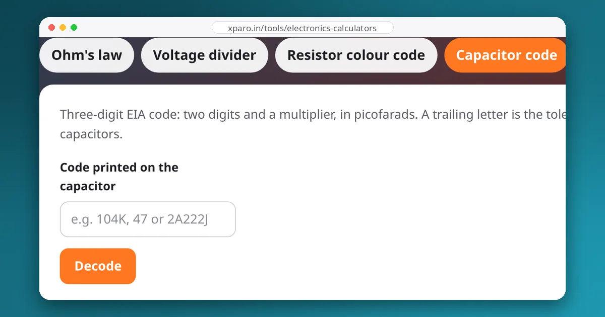
A letter after the code gives the tolerance: F ±1 %, G ±2 %, J ±5 %, K ±10 %, M ±20 %, Z +80/−20 %. Film capacitors often put a voltage code in front: 2A222J is a 2.2 nF, ±5 % capacitor rated 100 V (2A), and other common codes are 1H for 50 V, 2E for 250 V and 2J for 630 V. The capacitor code decoder understands all of these.
Electrolytic and tantalum capacitors
Larger capacitors print their value and voltage directly, such as 470 µF 25 V. Both types are polarised, and here is a trap: on aluminium electrolytics the stripe marks the negative lead, while on tantalum capacitors the stripe or bar marks the positive lead. A polarised capacitor fitted backwards can fail violently.
The main types and what they are good at
| Type | Typical values | Strengths | Weaknesses |
|---|---|---|---|
| Ceramic, C0G / NP0 | 1 pF – 100 nF | Very stable with voltage and temperature | Small values only |
| Ceramic, X7R / X5R | 1 nF – 100 µF | Small, cheap, very low ESR; ideal for decoupling | Capacitance drops with DC voltage and temperature |
| Ceramic, Y5V | large values | Cheap | Loses most of its capacitance in real conditions |
| Aluminium electrolytic | 1 µF – 10,000 µF+ | Large capacitance and voltage cheaply; bulk storage | Polarised, ages with heat, higher ESR |
| Polymer (aluminium or tantalum) | 10 µF – 1000 µF | Low ESR bulk capacitance | Cost; voltage limits |
| Film | 1 nF – 10 µF | Stable, tolerant of high voltage and current | Large for the value |
Class 2 ceramics (X7R, X5R) lose capacitance as DC voltage rises. A small 10 µF, 6.3 V capacitor can deliver less than half its marked value at 5 V. Choose a voltage rating well above the working voltage, or check the manufacturer's DC-bias curve.
Four jobs capacitors do on a robot
1. Decoupling every chip
Digital chips draw current in sharp pulses. A 100 nF ceramic capacitor between each power pin and ground, placed as close to the pin as possible, supplies those pulses locally so they do not travel along the board's power wiring. Leaving them out causes random resets and corrupted communication. On boards with a microcontroller, a 10 µF capacitor near the regulator adds a little bulk storage.
2. Bulk capacitance at motor drivers
Motor drivers pull large, fast current spikes every PWM cycle. Long battery wires have inductance and resistance, so without local storage the supply voltage at the driver bounces with every switching edge, which can reset the logic or even damage the driver. Fit a low-ESR electrolytic or polymer capacitor, typically somewhere between tens and hundreds of microfarads depending on the current, right at the driver's supply pins, and follow the driver datasheet's recommendation. Use a voltage rating comfortably above the battery's full-charge voltage.
3. Quieting brushed motors
The brushes of a DC motor spark as they switch, broadcasting electrical noise that upsets sensors and radios. A common fix is a 100 nF ceramic capacitor soldered directly across the motor terminals, and on noisy motors, two more of around 47 nF from each terminal to the motor's metal case. Keep the leads short and twist the motor wires together.
4. Filtering and timing
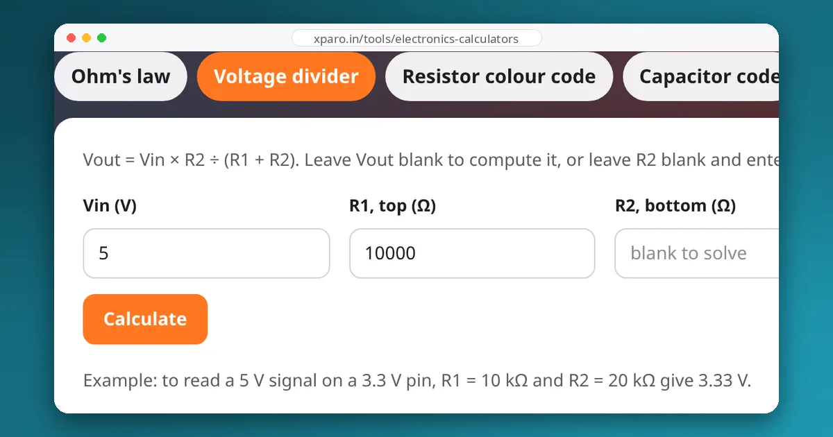
A resistor and capacitor form a low-pass filter or a timer with time constant τ = R × C. A 10 kΩ resistor with 100 nF gives 1 ms: enough to smooth an analog reading such as the battery voltage divider, or to debounce a bumper switch read by a slow loop.
Choosing a voltage rating
- Ceramic: at least 1.5 to 2 times the working voltage (more if you need the full capacitance).
- Aluminium electrolytic: at least 1.25 to 1.5 times the highest voltage, including a fully charged battery and motor regeneration spikes.
- Tantalum (MnO₂ type): derate to about half the rated voltage; they can fail short-circuit and burn if over-stressed by surge current.
A quick checklist for a robot board
- 100 nF ceramic at every chip's power pins, close to the pins.
- A regulator's input and output capacitors exactly as its datasheet specifies.
- Low-ESR bulk capacitance at each motor driver, rated above full battery voltage.
- Noise suppression capacitors on brushed motors.
- Polarity checked twice on every electrolytic and tantalum part.
Next, read our guide to 3.3 V and 5 V logic, the other classic source of mysterious robot faults.