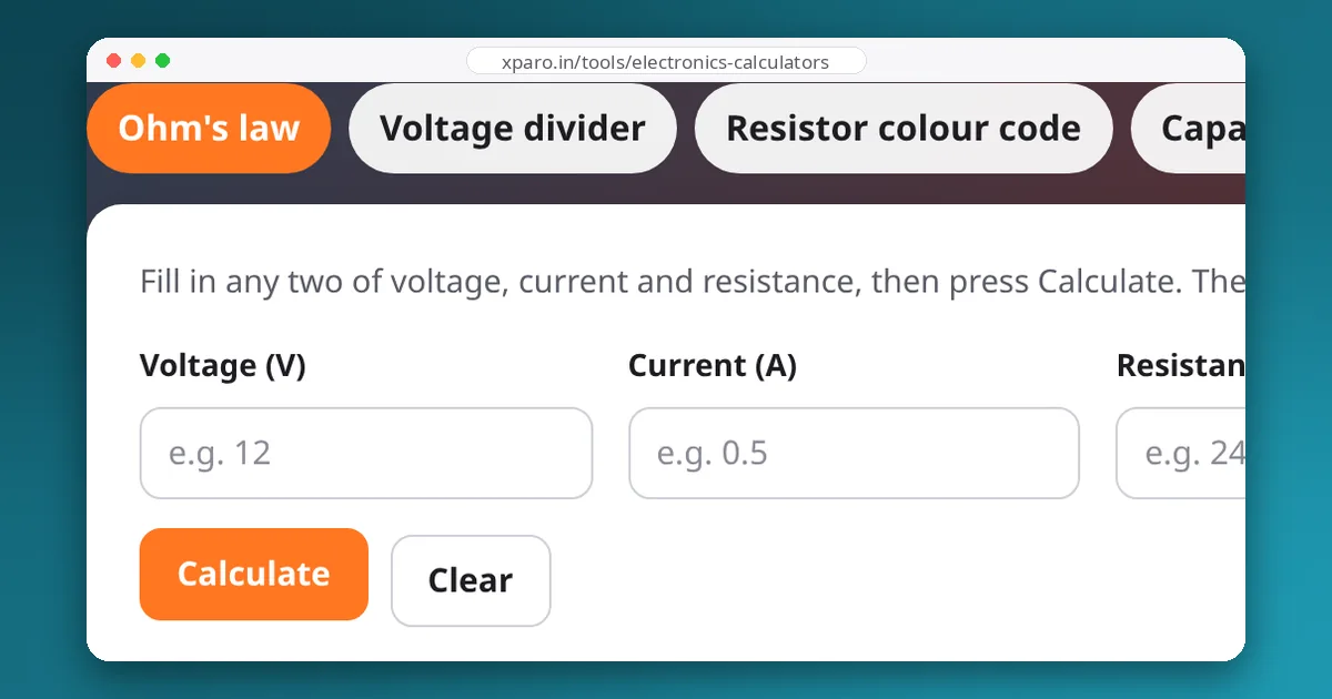
Ohm's law is the first formula anyone learns in electronics and the one robot builders use most. Paired with the power formula, it answers most everyday wiring questions: how big a resistor, how much current, how hot something will get, and why the robot slows down when the wires are too thin. Here are six problems you will meet on a real robot, worked through step by step.
The two formulas
If you know any two of voltage, current and resistance, you know the third. Power tells you how much energy becomes heat, which decides the size of the part. The Ohm's law calculator does both: enter two values and it fills in the third and the power, with units.
1. A resistor for a status LED
A red LED drops about 2.0 V when lit, and 10 mA makes it clearly visible. Driven from a 5 V microcontroller pin, the resistor must drop the remaining 3.0 V at 10 mA:
Now try a blue LED (about 3.0 V) on a 3.3 V pin. Only 0.3 V is left for the resistor, so small changes in the LED's actual forward voltage swing the current wildly. When the supply is barely above the LED voltage, drive the LED from a higher voltage through a transistor instead.
2. A pull-up resistor on a button
A bump switch connects a 3.3 V input to ground when pressed, with a 10 kΩ pull-up to 3.3 V keeping it high otherwise. The current while pressed is 3.3 ÷ 10,000 = 0.33 mA, negligible for any battery. A smaller pull-up gives a stiffer signal that resists electrical noise from motors, at the cost of a little more current; 4.7 kΩ to 10 kΩ is the usual range. The same logic applies to I2C pull-ups, where lower values give faster edges: 4.7 kΩ is common at 100 kHz, and around 2.2 kΩ at 400 kHz on a busy bus.
3. A shunt resistor to measure current
To measure up to 10 A, you put a 0.01 Ω shunt in series with the load and measure the voltage across it:
A 1 W resistor would run at its limit, so use a 2 W or 3 W part. A smaller shunt wastes less power but gives a smaller signal, which is why current-sense chips amplify it. Our guide to measuring current draw covers ready-made sensor boards.
4. A motor's stall current
Measure a brushed motor's winding resistance with a multimeter (rotate the shaft a little between readings and use a typical value). Suppose it reads 2.4 Ω. When the motor is stalled it produces no back-EMF, so at 12 V:
That is the current your motor driver and fuse must survive for the moments when a wheel jams or the robot starts against a wall. Running motors near stall for long periods overheats them; our guide to motor datasheets explains rated versus stall torque.
5. Voltage drop in the wiring
Wire has resistance too. 18 AWG copper wire has about 21 mΩ per metre. A motor 1 m from the battery uses 2 m of wire (out and back):
On a 12 V robot, 0.42 V is 3.5 percent of the supply lost before the motor sees it, plus 4 W of heat in the cable. Thicker wire (14 AWG, about 8 mΩ/m) cuts both by more than half. The battery safety guide has a full wire table.
6. Why a linear regulator gets so hot
A linear regulator such as the classic 7805 makes 5 V by burning the excess voltage as heat. Powering a 1 A load from a 12 V battery:
A TO-220 package without a heatsink typically has a thermal resistance of a few tens of °C per watt, so 7 W would push it far beyond its limit, and it shuts down or fails. This is why robots use switching (buck) converters for anything beyond small currents: a good buck converter does the same job at 85 to 95 percent efficiency.
Common mistakes
- Mixing units. Milliamps and kilo-ohms are easy to slip on. 5 V across 1 kΩ is 5 mA, not 5 A. Convert to volts, amps and ohms before calculating.
- Forgetting power. The right resistance at the wrong power rating still burns. Use a part rated for at least twice the calculated power.
- Applying Ohm's law to non-linear parts. LEDs, diodes and spinning motors are not resistors. Use their voltage drop (LED, diode) or back-EMF (motor) first, then apply Ohm's law to what is left.
- Ignoring the source. Batteries and long cables have resistance too. Under heavy load, the voltage you planned with is not the voltage you get; see C-ratings and voltage sag.