Knowing the battery voltage lets a robot go home before it dies, log its health and warn you about a failing pack. The cheapest way to measure it is two resistors and a microcontroller's analog input. Doing it accurately and safely takes a little more thought: the divider ratio, the ADC's input impedance, calibration and protection. This guide covers all four for Arduino and ESP32 boards.
Why you need a divider
A microcontroller's analog-to-digital converter (ADC) can only measure voltages up to its reference: 5 V on an Arduino Uno, roughly 2.5 to 3.1 V on an ESP32 depending on the chip and settings. A 4S lithium pack reaches 16.8 V when full. Two resistors in series scale it down:
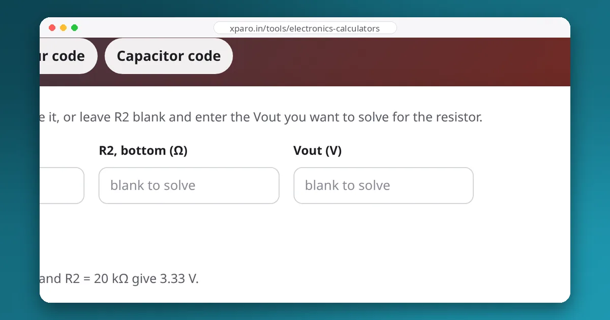
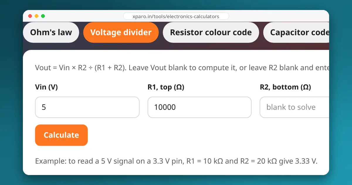
R1 is the top resistor from the battery, R2 the bottom one to ground, and the ADC pin connects to the middle. The voltage divider calculator solves for either the output or the R2 you need.
Step 1: pick the ratio
Start from the highest voltage the battery can ever reach (a full charge, plus a margin for a charger connected while the robot runs) and the highest voltage your ADC measures accurately. For a 4S LiPo on an original ESP32, whose recommended input range at its highest attenuation setting is roughly 0.15 to 2.45 V:
For a 3S pack (12.6 V full) on a 5 V Arduino Uno, R1 = 20 kΩ and R2 = 10 kΩ give 4.2 V at full charge.
Step 2: mind the ADC's input impedance
A successive-approximation ADC, the kind in almost every microcontroller, charges a small internal sampling capacitor through whatever drives the pin. If the source is high-impedance, the capacitor does not fully charge in the sampling time and readings come out low and noisy. The ATmega328P datasheet, for example, says its ADC is optimised for sources of about 10 kΩ or less.
The source impedance of a divider is R1 and R2 in parallel: for 100 kΩ and 15 kΩ, that is about 13 kΩ. Two easy fixes:
- Add a capacitor of about 100 nF from the ADC pin to ground. It holds the voltage steady and supplies the sampling charge. Battery voltage changes slowly, so the RC time constant (about 1.3 ms here) costs nothing.
- Use smaller resistors with the same ratio, such as 20 kΩ and 3 kΩ. The divider then wastes more current, which is the trade-off.
Step 3: check the current it wastes
The divider draws current all the time:
For a robot's main pack, this is nothing. For a robot stored for months, or a tiny battery-powered sensor, switch the divider off with a MOSFET when not measuring, or use much larger resistors with the capacitor from step 2.
Step 4: calibrate
Resistor tolerances and ADC errors add up. Two 1 % resistors can shift the ratio by almost 2 % in the worst case, which is about 0.3 V on a 16.8 V pack, enough to matter when a lithium cell's whole useful range is about 1 V. Calibrate once:
- Measure the battery with a good multimeter and note the ADC reading (or millivolts) at the same moment.
- Repeat at a second, clearly different voltage (for example full and half empty).
- Fit a straight line: battery voltage = gain × reading + offset, and store the two numbers in your firmware.
On ESP32 boards, read the pin with analogReadMilliVolts() in the Arduino core instead of the raw value. It applies the chip's factory calibration, which corrects much of the ESP32 ADC's well-known non-linearity. Also use an ADC1 pin: on the original ESP32, ADC2 cannot be used while Wi-Fi is running.
Example code
// ESP32 (Arduino core): 4S pack through 100k / 15k, 100 nF on the pin
const int   BATT_PIN = 34;                    // an ADC1 pin
const float SCALE    = (100.0 + 15.0) / 15.0; // 7.667, then calibrate
const float GAIN     = 1.000;                 // from your two-point calibration
const float OFFSET   = 0.000;                 // volts

float readBattery() {
  uint32_t sum = 0;
  for (int i = 0; i < 16; i++) sum += analogReadMilliVolts(BATT_PIN);  // average 16 samples
  float pinVolts = sum / 16.0 / 1000.0;
  return GAIN * pinVolts * SCALE + OFFSET;
}

void setup() { Serial.begin(115200); }

void loop() {
  Serial.print("battery:");
  Serial.println(readBattery(), 2);
  delay(500);
}
The output uses the name:value format, so the Web Serial Monitor plots it directly. Averaging several samples, as above, removes most of the ADC's noise.
Step 5: protect the pin
Most microcontroller pins tolerate only a fraction of a volt beyond their supply rails. The divider's top resistor already limits current if something goes wrong; with 100 kΩ, even a 30 V spike pushes only 0.3 mA into the pin's internal clamp diodes. For extra safety on noisy motor power, add a small Schottky diode from the pin to the 3.3 V rail, or a zener or TVS diode to ground, and make sure the bottom resistor connects to ground before the top one connects to the battery (for example, solder the divider rather than relying on a plug that might mate the battery wire first).
Reading the result
Under load, the battery voltage sags, so the same pack reads lower while driving than at rest (see C-ratings and voltage sag). For a state-of-charge estimate, use readings taken while the robot is idle, or filter heavily. For LiFePO4 packs, whose voltage is nearly flat over most of their range, voltage alone is a poor fuel gauge; count charge with a current sensor instead.
No ADC? Use an external one
A Raspberry Pi has no analog inputs. Add an I2C ADC such as the ADS1115 (16-bit) behind the same divider, or use a current and voltage monitor chip such as the INA219 or INA226, which also measures current, as described in our guide to measuring current draw.