Modern robots mix logic voltages. A Raspberry Pi and an ESP32 speak 3.3 V; an Arduino Uno, many motor drivers, ultrasonic sensors and LED strips speak 5 V. Connecting them directly sometimes works, sometimes fails intermittently, and sometimes destroys a pin. This guide explains when you need a level shifter and which kind to use for each type of signal.
Two separate problems
Level shifting is really two questions, one for each direction:
- 5 V into a 3.3 V input: is it safe? Usually not. Pins on the Raspberry Pi, ESP32 and most 3.3 V microcontrollers are not 5 V tolerant. Their absolute maximum is roughly the supply voltage plus 0.3 V. A 5 V signal forces current through the pin's protection diodes and can damage the chip, immediately or slowly. (Some chips, such as many STM32 parts, have specific 5 V-tolerant pins marked in the datasheet; check before relying on it.)
- 3.3 V into a 5 V input: is it reliable? It is safe, but whether a 3.3 V "high" is recognised depends on the receiving chip's input threshold.
Reading the thresholds
Every digital input has a minimum voltage it guarantees to read as high, VIH. Compare it with the sender's minimum high output, VOH:
| Receiver (at 5 V) | VIH minimum | 3.3 V output works? |
|---|---|---|
| ATmega328P (Arduino Uno) digital pins | 0.6 × VCC = 3.0 V | Usually, but with little margin |
| 74HC logic (CMOS inputs) | about 3.5 V | No, not guaranteed |
| 74HCT / 74AHCT logic (TTL-level inputs) | 2.0 V | Yes, comfortably |
| WS2812-style addressable LEDs | 0.7 × VDD = 3.5 V | Often flickers or fails; shift it |
The Uno case is the dangerous one: it works on the bench and fails on a robot where motor noise and voltage drops eat the 0.3 V margin. If a link matters, shift it.
Option 1: a resistor divider (5 V to 3.3 V only)
For a signal that only goes from a 5 V device to a 3.3 V input, such as a GPS module's TX line into a Raspberry Pi, two resistors are enough:
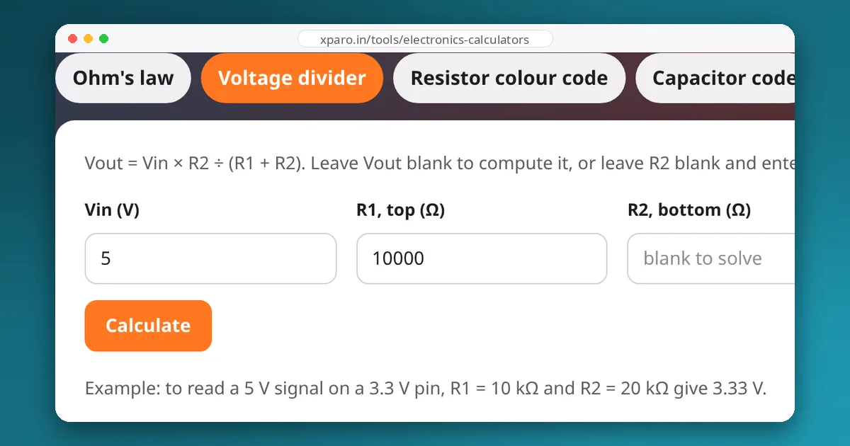
The resistors and the input's capacitance form a low-pass filter. With 1 kΩ and 2 kΩ, the equivalent resistance is about 670 Ω, fast enough for UART and slow SPI. With 10 kΩ and 20 kΩ, edges slow to tens of nanoseconds, which limits you to roughly a few MHz. The voltage divider calculator works out other combinations.
A divider cannot shift up, and it does not work for bidirectional lines.
Option 2: a MOSFET shifter (bidirectional, open-drain buses)
The popular small level-shifter boards use one N-channel MOSFET (typically a BSS138) and two pull-up resistors per channel, a circuit described in an old Philips application note for I2C. Either side can pull the line low, and the pull-ups set each side's high level, so it works in both directions. It is the right choice for I2C and other open-drain signals. Its speed is limited by the pull-up resistors charging the line capacitance, which is fine for 100 and 400 kHz I2C but poor for fast push-pull signals such as SPI at several MHz.
Option 3: a buffer chip (fast, one direction)
For fast signals in one direction, use a logic buffer powered at the receiver's voltage:
- 3.3 V to 5 V: a 74AHCT125 or 74HCT245 powered at 5 V. Their TTL-level inputs accept 3.3 V as high, and their outputs swing to 5 V. This is the standard fix for driving WS2812 LED strips from an ESP32 or Raspberry Pi.
- 5 V to 3.3 V: a 74LVC245 or 74LVC125 powered at 3.3 V. LVC inputs tolerate 5 V even when the chip runs at 3.3 V.
These handle SPI clocks of tens of MHz, servo PWM and encoder signals with clean edges.
Option 4: auto-direction translators
Chips such as the TXB0108 and TXS0108E sense the direction automatically. They are convenient but particular: the TXB family is meant for push-pull signals and misbehaves with pull-up resistors (so not for I2C), while the TXS family tolerates open-drain lines but has weak drive. Read the datasheet's application notes before using them on long wires or noisy robots.
Which shifter for which signal?
| Signal | Direction | Good choice |
|---|---|---|
| UART TX from a 5 V device to a 3.3 V board | down | Resistor divider (1 k / 2 k) |
| UART TX from a 3.3 V board to a 5 V device | up | Often works direct (check VIH); otherwise a 74AHCT buffer |
| I2C between 3.3 V and 5 V devices | both | MOSFET (BSS138) shifter |
| SPI to a 5 V peripheral | both, separate lines | 74AHCT125 (up) and 74LVC125 or a divider for MISO (down) |
| WS2812 / NeoPixel data | up | 74AHCT125 powered at 5 V |
| HC-SR04 ultrasonic echo into a Pi or ESP32 | down | Resistor divider |
| Quadrature encoder (5 V) into a 3.3 V MCU | down | 74LVC buffer or divider; keep edges sharp |
Practical tips
- Share a ground. A level shifter translates voltages relative to ground. Without a common ground between the two boards, nothing works reliably.
- Power the shifter's sides correctly. Shifter boards have a low-voltage (LV) and high-voltage (HV) supply pin. Swapping them is a common mistake.
- Do not shift power. A level shifter carries signals, not supply current. Power 5 V devices from a 5 V regulator.
- Check open-collector outputs. Some sensors have open-collector or open-drain outputs. Pull them up to the receiver's voltage and no shifter is needed.
- Debug with the serial monitor. Garbled UART data between boards at different voltages is often a level or ground problem rather than a baud-rate problem; our guide to serial debugging helps tell them apart.