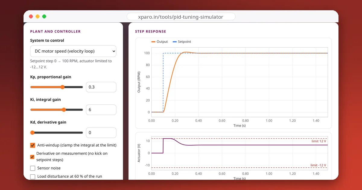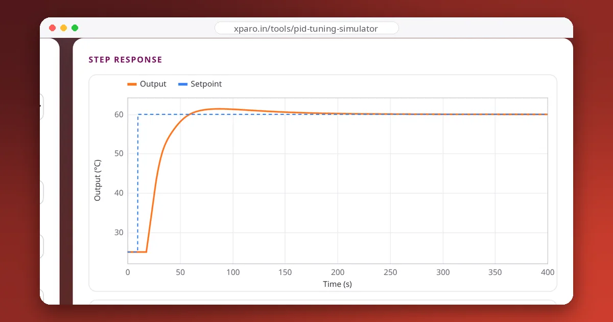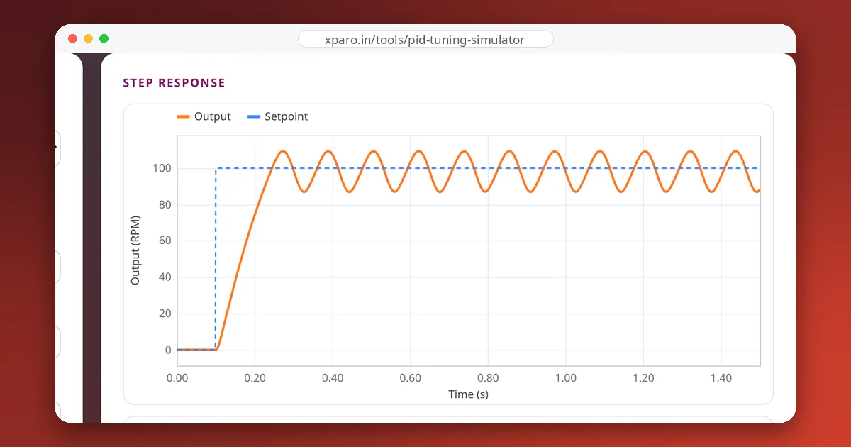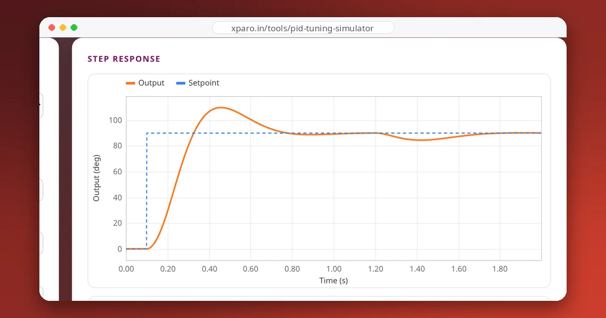
The PID equation in a textbook assumes an actuator that can deliver any value, a measurement without noise, and a setpoint that never jumps. Real robots have none of these. Three well-known problems follow: integral windup, derivative kick and noise amplification. Each has a standard fix, and we measured how much each fix matters with our PID Tuning Simulator.
1. Integral windup
What happens
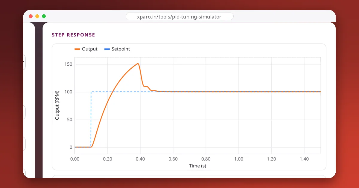
Every actuator has limits: a motor driver can't give more than the battery voltage, a heater can't exceed 100 %. During a large move, the controller asks for more than the actuator can give, and the output sits at its limit. The error stays large the whole time, so the integral term keeps growing, or "winding up". When the output finally reaches the target, the integral is enormous and keeps pushing, so the system overshoots far past the target and takes a long time to unwind.
How much it matters
We ran the same gains with anti-windup off and on:
| Simulator system and gains | Overshoot without anti-windup | With anti-windup |
|---|---|---|
| Motor speed, Kp 2, Ki 60 | 51 % | 0 % |
| Heater, Ziegler-Nichols PID (4.97 / 0.327 / 18.9) | 73 % | 9 % |
| Mass on a spring, Kp 400, Ki 900, Kd 30 | 26 % | 1 % |
Same gains, same system; the only difference is a few lines of code.
The fixes
- Clamping (conditional integration): stop integrating whenever the output is saturated and the error would push it further into saturation. Simple and effective; it is what the simulator and the Python class in our PID introduction use.
- Back-calculation: feed the difference between the requested and the actual (saturated) output back into the integrator, scaled by a gain, so the integral unwinds while saturated. Common in industrial controllers.
- Integrator limits: cap the integral term itself. Better than nothing, but the right limit depends on the load.
Also reset or re-initialise the integral whenever the controller is switched off or changes mode, so stale integral from the last run does not cause a jump ("bumpless transfer").
2. Derivative kick
What happens
The derivative term responds to the rate of change of the error. When the setpoint jumps, the error jumps instantly, and its derivative is huge for one sample. The controller output gets a spike, the "kick".
How big is it?
In the simulator's position loop (Kp 0.22, Kd 0.012, a step from 0 to 90°, 1 kHz loop), the controller's unclipped command at the moment of the step was 236 V with derivative on the error, against 19.8 V (just the P term) with derivative on the measurement. Here the 12 V driver limit hides most of the kick, but with smaller steps, or an actuator that responds to every spike (a valve, a servo, a motor that jerks the robot), it reaches the hardware.
The fix
Take the derivative of the measurement instead of the error, with the sign flipped:
When the setpoint is constant, the two are identical, so damping is unchanged. When the setpoint jumps, the measurement does not, so there is no kick. Ramping the setpoint instead of stepping it helps too, and is kinder to the mechanics.
3. Noise amplification
What happens
Differentiation amplifies fast changes, and sensor noise is nothing but fast changes. An encoder that flickers by one count, or a temperature sensor with a little jitter, turns into large, rapid swings in the derivative term, and the actuator chatters.
How much it matters
With sensor noise switched on in the simulator, we measured the standard deviation of the heater's power once it had settled:
| Controller | Heater power jitter |
|---|---|
| PI only (Kd = 0) | 1.3 % |
| PID, Kd = 18.9, no derivative filter | 8.8 % |
| PID, Kd = 18.9, 2 s derivative filter | 2.0 % |
The fixes
- Filter the derivative with a first-order low-pass filter. A common choice is a filter time constant of Td ÷ N with N between about 5 and 20. Too much filtering adds lag and erodes the damping D was meant to provide.
- Improve the measurement where it is cheap: more encoder resolution, a better speed estimate, shielding and proper grounding of sensor wires.
- Use less D. Many robot loops work well as PI loops with no derivative at all.
A robust PID checklist
- Clamp the output to the actuator's real limits.
- Use anti-windup (clamping or back-calculation).
- Take D from the measurement, and filter it.
- Run at a fixed rate, and use the actual
dt. - Reset the integral when the loop is disabled or changes mode.
- Ramp large setpoint changes when the mechanics allow it.
Every row in the tables above can be reproduced in the simulator: pick the system, type the gains, and toggle anti-windup, derivative on measurement, noise and the derivative filter. Then apply the same fixes to a real motor in our guide to closed-loop motor speed control.