Almost every wheeled robot depends on one small control loop: holding each wheel at the speed the navigation stack asks for, regardless of load, slope and battery voltage. This guide builds that loop for a DC gearmotor with an encoder: measuring speed, choosing the loop rate, adding feedforward, and tuning, with a complete Arduino sketch you can adapt.
The pieces
- A DC gearmotor with a quadrature encoder. The encoder produces two square waves, A and B, a quarter cycle apart; counting edges gives position, and which channel leads gives direction.
- A motor driver (an H-bridge) taking a direction signal and a PWM duty cycle.
- A microcontroller that counts encoder edges in an interrupt and runs the control loop at a fixed rate.
Measuring speed from an encoder
The simplest estimate counts edges over a fixed interval:
Counts per revolution must be measured at the output shaft and must match how you decode. A typical small gearmotor's encoder gives 11 pulses per motor revolution per channel; through a 30:1 gearbox that is 330 pulses per wheel revolution. Counting both edges of channel A doubles it to 660; counting every edge of both channels (full quadrature) gives 1320.
The catch is quantisation. Each estimate is a whole number of counts, so at low speed and short intervals the reading is coarse:
| Encoder (counts per wheel revolution) | Loop rate | Counts per sample at 60 RPM | One count is |
|---|---|---|---|
| 660 | 100 Hz | 6.6 | 15 % of the reading |
| 1320 | 100 Hz | 13.2 | 7.6 % |
| 1320 | 1 kHz | 1.3 | 76 % |
So a faster loop is not automatically better: at 1 kHz this encoder can barely tell speeds apart. Use full quadrature decoding where you can, filter the estimate lightly, and at very low speeds measure the time between edges instead of counting them.
Choosing the loop rate
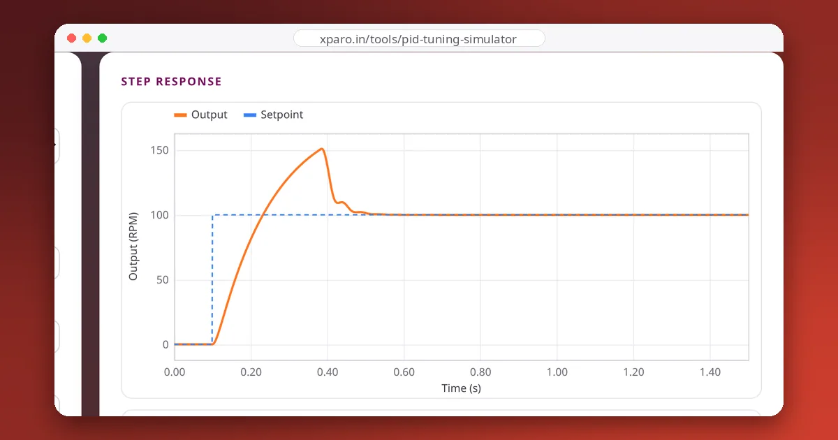
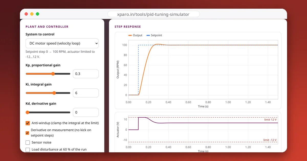
The loop must be several times faster than the motor's own response. A small gearmotor with a wheel typically reaches speed in a few hundred milliseconds, so 50 to 200 Hz is plenty. In our simulator's motor speed loop (a 0.15 s mechanical time constant), the same PI gains settle in 145 ms whether the loop runs at 1000 Hz or 100 Hz. Pick a rate your encoder can support and keep it exactly constant.
Feedforward does most of the work
A DC motor's steady speed is roughly proportional to its voltage, plus a small offset to overcome friction. If you know that relationship, you can command roughly the right PWM directly and leave the PID to correct the remainder:
Measure KV and KS once: apply several fixed PWM values with the wheel on the ground, record the steady speeds, and fit a straight line. KS is the PWM where the wheel just starts moving; KV is the slope. With good feedforward, the robot responds to speed changes almost instantly, and the integral only has to handle load and battery variation.
The sketch
// Speed control of one DC gearmotor with a quadrature encoder:
// feedforward + PI with clamping anti-windup, at a fixed 100 Hz.
const int ENC_A = 2, ENC_B = 3;        // encoder channels (pin 2 can interrupt on an Uno)
const int PWM_PIN = 9, DIR_PIN = 8;    // motor driver inputs
const float COUNTS_PER_REV = 660.0;    // both edges of channel A, 11 PPR x 30:1 gearbox
const unsigned long PERIOD_US = 10000; // 100 Hz control loop
const float KV = 255.0 / 180.0;        // feedforward: PWM per RPM (full PWM gave about 180 RPM)
const float KS = 20.0;                 // PWM needed just to overcome friction
const float KP = 1.2, KI = 8.0;        // start here, then tune on your motor

volatile long encoderCount = 0;
float targetRpm = 0;

void onEncoderA() {
  // count both edges of channel A; the level of B gives the direction
  if (digitalRead(ENC_A) == digitalRead(ENC_B)) encoderCount--; else encoderCount++;
}

void setup() {
  pinMode(ENC_A, INPUT_PULLUP);
  pinMode(ENC_B, INPUT_PULLUP);
  pinMode(DIR_PIN, OUTPUT);
  attachInterrupt(digitalPinToInterrupt(ENC_A), onEncoderA, CHANGE);
  Serial.begin(115200);
}

void loop() {
  static unsigned long last = micros();
  static long lastCount = 0;
  static float integral = 0, rpmFiltered = 0;

  if (Serial.available()) targetRpm = Serial.parseFloat();   // type a speed, e.g. 120

  unsigned long now = micros();
  if (now - last < PERIOD_US) return;
  float dt = (now - last) * 1e-6;
  last = now;

  noInterrupts();
  long count = encoderCount;
  interrupts();
  float rpm = (count - lastCount) / COUNTS_PER_REV / dt * 60.0;
  lastCount = count;
  rpmFiltered += 0.3 * (rpm - rpmFiltered);                  // light low-pass filter

  float error = targetRpm - rpmFiltered;
  float ff = 0;
  if (targetRpm > 0) ff = KV * targetRpm + KS;
  if (targetRpm < 0) ff = KV * targetRpm - KS;

  float candidate = integral + KI * error * dt;
  float unclamped = ff + KP * error + candidate;
  bool pushingFurther = (unclamped > 255 && error > 0) || (unclamped < -255 && error < 0);
  if (!pushingFurther) integral = candidate;                  // clamping anti-windup
  if (targetRpm == 0) integral = 0;                           // stop cleanly

  float out = constrain(ff + KP * error + integral, -255, 255);
  digitalWrite(DIR_PIN, out >= 0 ? HIGH : LOW);
  analogWrite(PWM_PIN, (int)fabs(out));

  Serial.print("target:"); Serial.print(targetRpm);
  Serial.print(",rpm:");   Serial.print(rpmFiltered);
  Serial.print(",pwm:");   Serial.println(out);
}
The serial output uses name:value pairs, so the Web Serial Monitor plots target, speed and PWM live while you type new targets. If the wheel runs away when you first enable the loop, the encoder direction is reversed relative to the motor: swap A and B, or flip the sign of the count.
Tuning it
- Tune feedforward first, with KP and KI at zero: commanded speeds should already come out roughly right.
- Add KP until speed changes are crisp without oscillation.
- Add KI until the speed holds under load (press on the wheel, drive up a ramp).
- Repeat at low battery. The PWM needed for a given speed rises as the voltage falls, and a well-tuned loop compensates; if it can't, scale the PWM by nominal voltage ÷ measured voltage.
Try the same steps in the PID Tuning Simulator's motor speed loop first; the tuning guide explains the method in detail.
Practical details
- PWM frequency: the Arduino default (about 490 Hz on pin 9 of an Uno) makes motors whine. Drivers and timers set to around 20 kHz are inaudible; check your driver's maximum.
- Both wheels the same way: on a differential-drive robot, identical loops on both wheels matter more than perfect tuning on either. Mismatched loops make the robot curve.
- Talking to ROS 2: the microcontroller receives wheel speed targets and reports encoder counts, through micro-ROS, a ros2_control hardware interface, or a simple serial protocol such as the one in our guide to microcontroller-to-ROS serial links. The conversion from
cmd_velto wheel speeds is covered in from cmd_vel to wheel speeds.