How to use the PID tuning simulator
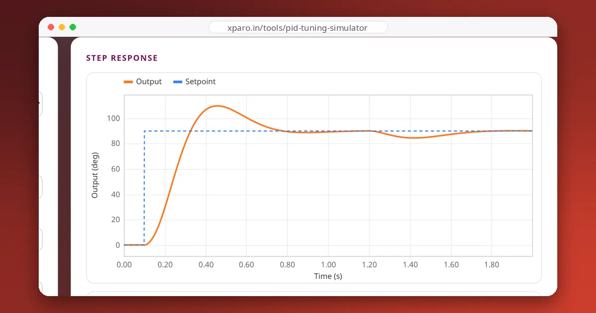
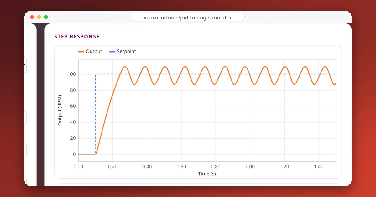
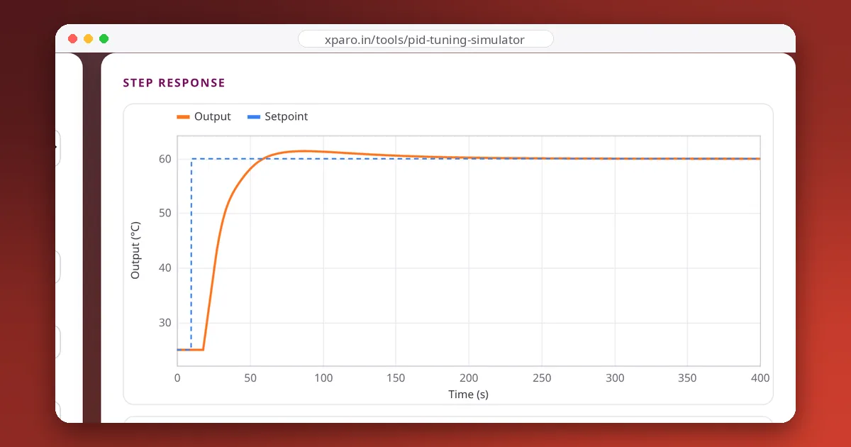
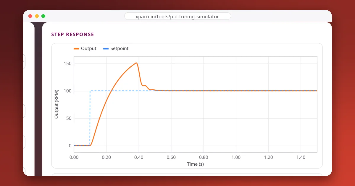
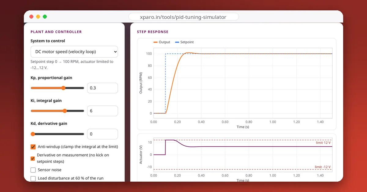
- Pick a system. Four plants behave like hardware you meet on robots: a DC motor speed loop, a motor position (servo) loop, a heater with dead time, and a lightly damped mass on a spring. Each has a realistic actuator limit: 12 V for the motors, 0 to 100 % for the heater, ±20 N for the spring.
- Start from a preset. Each preset demonstrates one behaviour, and the note under the buttons explains what to look for.
- Drag the gains. The sliders are logarithmic, so small values are easy to reach, and the number boxes take exact values. The response redraws as you move.
- Stress the tuning. Turn on sensor noise and the load disturbance. A tuning that only looks good on a clean step often falls apart here.
- Compare. Pin a response you like, keep adjusting, and the pinned curve stays on the chart as a dashed grey line. Copy link saves the exact settings in the URL.
What the simulator computes
The controller is the standard parallel PID, run at the loop rate you choose and held constant between updates (zero-order hold), exactly like a timer interrupt on a microcontroller:
With anti-windup on, the integral stops accumulating whenever the output is already saturated and the error would push it further, which is the clamping method used in most embedded controllers. The plants are simulated with a fourth-order Runge-Kutta integrator at a much finer time step than the controller, so what you see is the controller's behaviour, not integration error.
Reading the numbers
| Metric | Meaning | If it is too high |
|---|---|---|
| Rise time | Time from 10 % to 90 % of the step | Raise Kp (if the actuator is not already saturating) |
| Overshoot | How far the output goes past the setpoint, as a percentage of the step | Lower Kp or Ki, or add Kd |
| Settling time | Time until the output stays within 2 % of the setpoint | Add damping (Kd) or reduce Ki |
| Steady error | Average error near the end, before any load is applied | Add Ki |
| Saturated | Share of the run the actuator spends at its limit | Expect windup; enable anti-windup or lower the gains |
| Error under load | Error left after the load disturbance | Only the integral removes it: raise Ki |
A quick tuning recipe
- Set Ki and Kd to zero. Raise Kp until the response is quick with a little overshoot.
- Add Kd until the overshoot shrinks. Stop if the controller output turns noisy once sensor noise is on.
- Add Ki until the steady error disappears in a reasonable time, then back off if overshoot returns.
- Turn on noise and the disturbance, and check that the tuning still behaves. Keep anti-windup on.
The plants are simple models. Use the simulator to build intuition and to find the right order of magnitude, then finish tuning on the real system, starting with lower gains than you think you need.