How to use the differential drive calculator
- Measure the geometry. Enter the wheel diameter and the wheel separation, the distance between the centres of the two tyres' contact patches. The defaults (66 mm wheels, 160 mm apart) are typical of small TurtleBot-style robots.
- cmd_vel → wheels. Enter the linear and angular speed from a
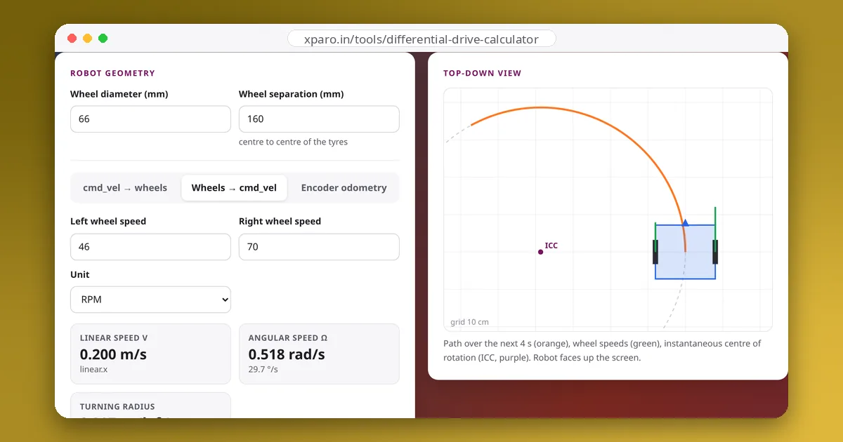
geometry_msgs/Twistand get each wheel's speed in m/s, rad/s, RPM and encoder ticks per second. Add your motors' top speed to see how the command is scaled when a wheel would exceed it. - Wheels → cmd_vel. Enter measured wheel speeds to get the robot's actual linear and angular velocity, for example to check that a driver obeys its command.
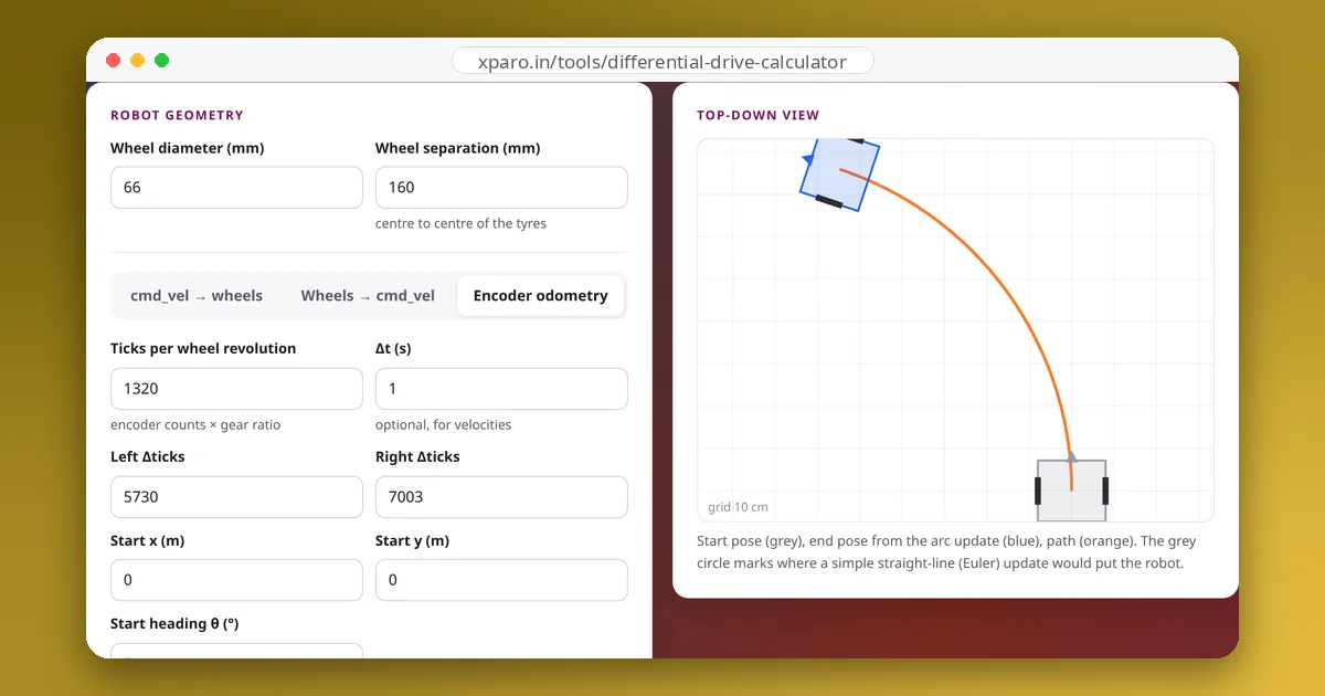
- Encoder odometry. Enter the tick counts since the last update and the start pose to get the new pose, the way an odometry node computes it.
The kinematics
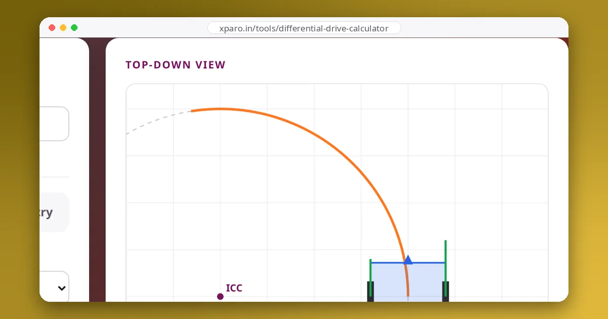
A differential-drive robot moves on a circle around its instantaneous centre of rotation (ICC), which lies on the line through both wheel axles. With wheel radius r and wheel separation L:
Worked example
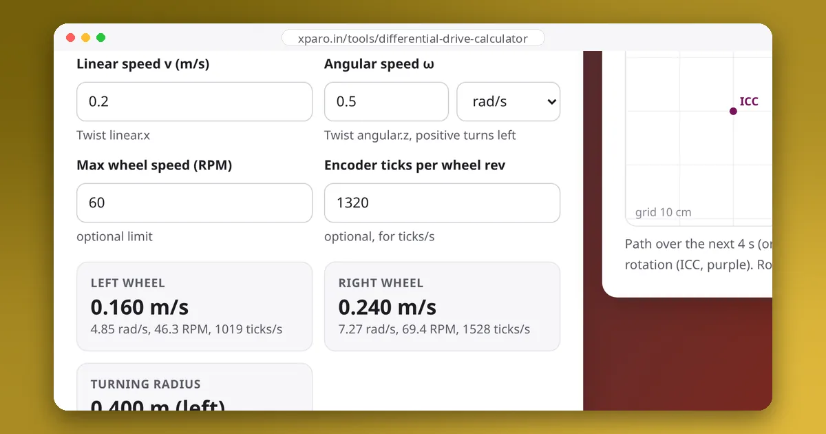
Commanding v = 0.2 m/s and ω = 0.5 rad/s on the default robot (r = 33 mm, L = 160 mm) gives v_left = 0.2 − 0.5 × 0.08 = 0.16 m/s and v_right = 0.24 m/s. Dividing by the radius: 4.85 rad/s (46 RPM) and 7.27 rad/s (69 RPM). The turning radius is 0.2 ÷ 0.5 = 0.4 m, to the left. With a 60 RPM limit, the right wheel is too fast, so both commands are scaled by about 0.86 and the robot drives the same 0.4 m circle a little slower.
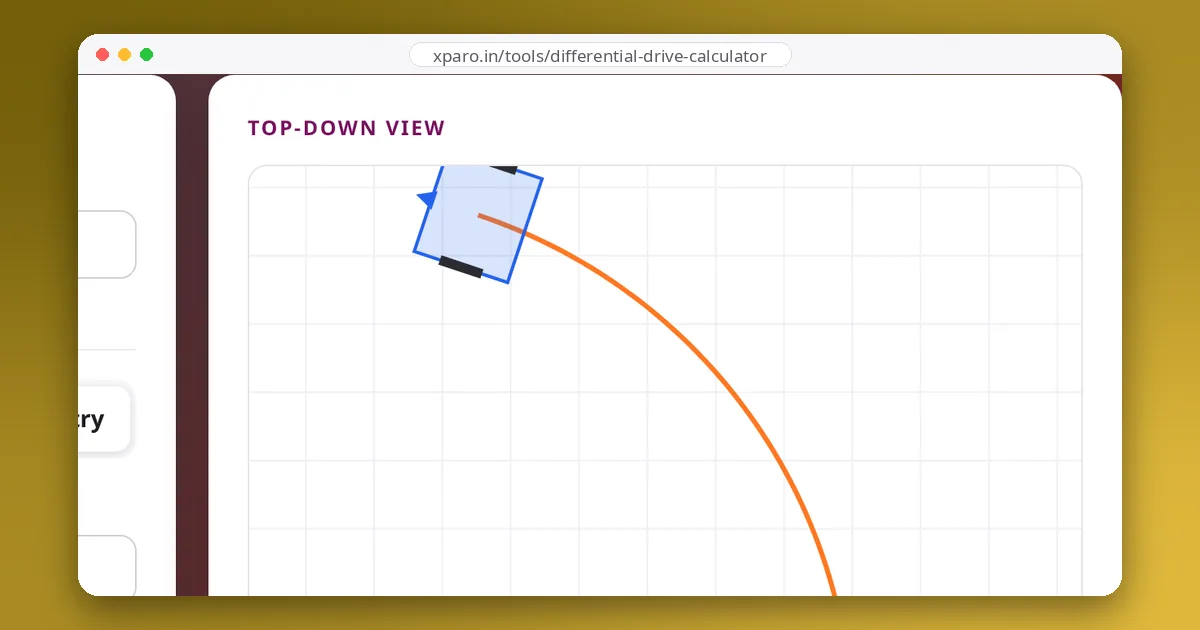
In the odometry tab, the defaults describe one second in which the left wheel turned 5730 ticks and the right 7003. That is 0.9 m and 1.1 m of travel, so the robot moved 1.0 m along an arc and turned 1.25 rad (71.6°). The arc update puts it at (0.759, 0.548); a simple straight-line update would put it at (1.0, 0), about 60 cm away. Running odometry at a high rate keeps each step small, and the arc update keeps it accurate even when steps are large.
Tips
- Measure separation where the tyres touch the floor. Wide or soft tyres, and every skid-steer robot, behave as if the wheels were further apart than they are. Calibrate it with a rotation test rather than a ruler.
- Count ticks per wheel turn, not per motor turn. Multiply the encoder's counts per revolution by the gear ratio, and by 4 if you count every edge of a quadrature encoder.
- Keep signs straight. In ROS, positive angular.z turns left (counter-clockwise seen from above). If your robot turns right, swap the motor wires or invert one wheel in software.