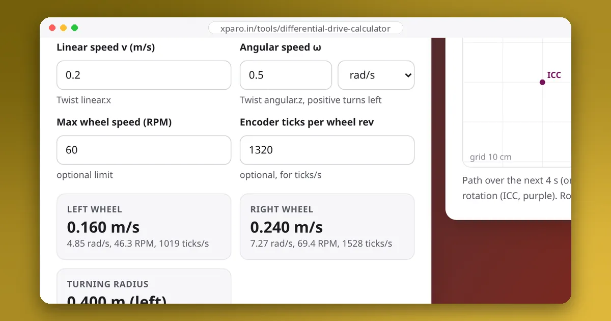
Every mobile robot needs limits on speed and acceleration: motors have a top speed, tyres have limited grip, and a tall robot tips over if it brakes too hard. The obvious way to apply a limit, clamping each number on its own, quietly changes the path the robot drives. This guide shows how much, using measurements from ROS 2 Jazzy's diff_drive_controller and Nav2's velocity smoother, and how to limit motion without bending the path.
Clamping changes the curve
A differential-drive robot's path is set by the ratio of turn rate to speed. The turning radius is R = v ÷ ω, so a command of v = 0.20 m/s and ω = 0.50 rad/s means "drive a circle 0.40 m in radius". Change v or ω on its own and you change the circle.
Take a small robot with 33 mm wheels, 160 mm apart, and motors that top out at 60 RPM (6.28 rad/s). That command asks for 4.85 rad/s on the left wheel and 7.27 rad/s on the right, more than the right motor can do. There are two ways to handle it:
| v (m/s) | ω (rad/s) | Turning radius | |
|---|---|---|---|
| Command | 0.200 | 0.500 | 0.40 m |
| Clip the right wheel to 6.28 rad/s | 0.184 | 0.296 | 0.62 m |
| Scale both wheels by 0.864 | 0.173 | 0.432 | 0.40 m |
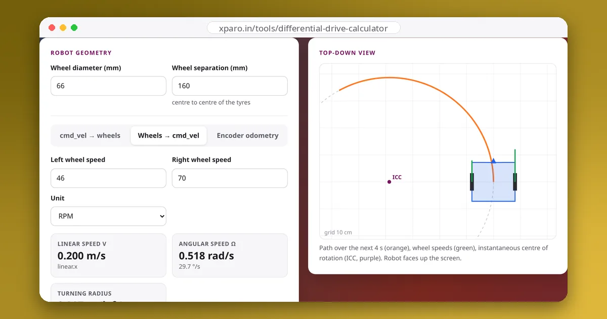
Clipping one wheel turns a 0.40 m curve into a 0.62 m one, which can carry the robot outside the corridor the planner checked for collisions. Scaling both wheels by the same factor slows the robot down but keeps it on the curve. The cmd_vel → wheels tab of the Differential Drive Calculator does this for you: enter your motors' top speed and it shows the scaled command.
Choosing the numbers
Velocity limits come from the motors: the no-load speed of the gearmotor, minus a margin for battery sag and load. Acceleration limits come from whichever of three things gives out first:
Here μ is the tyre's friction coefficient, h the height of the centre of mass and d its horizontal distance to the wheel or caster the robot would tip over. For a 10 kg robot with μ = 0.6 and 70% of its weight on the driven wheels, traction allows 4.1 m/s². With the centre of mass 0.25 m up and 0.10 m from the caster, tipping allows 3.9 m/s². Two motors giving 0.8 N·m each at 50 mm wheels allow 3.0 m/s². Then set the limit well below the smallest of these, because payloads shift, floors get dusty and batteries sag. For a tall or loaded indoor robot, 0.5 to 1 m/s² is a sensible place to start; Nav2's example configuration uses 2.5 m/s², which is a lot for such a robot. The forces guide and the Motor Sizing Calculator cover the torque side in detail.
Deceleration deserves its own number. At 0.5 m/s, braking at 1.0 m/s² takes 0.5 s and 12.5 cm; at 0.3 m/s² it takes 1.7 s and 42 cm. Your safety distances, and the collision checks in your planner, must allow for it.
What diff_drive_controller does
The ros2_control diff_drive_controller limits linear.x and angular.z separately. On Jazzy, a limit is active as soon as you give it a value; the old has_velocity_limits-style switches are deprecated. This is the configuration we tested with mock hardware:
diff_drive_controller:
  ros__parameters:
    # wheel names, wheel_radius: 0.033, wheel_separation: 0.16 ...
    publish_limited_velocity: true   # publish what was actually sent on ~/cmd_vel_out
    linear.x.max_velocity: 0.15
    linear.x.max_acceleration: 0.5
    linear.x.max_deceleration: -1.0  # must be zero or negative
    angular.z.max_velocity: 1.0
    angular.z.max_acceleration: 1.0
Deceleration limits are written as negative numbers. With linear.x.max_deceleration: 1.0 the controller refuses to load ("must be less than or equal to '0'"). If you leave the deceleration out, the acceleration value is used for braking too, and an unset minimum velocity defaults to minus the maximum.
We then commanded v = 0.20 m/s and ω = 0.50 rad/s (a 0.40 m circle) and recorded ~/cmd_vel_out:
| Time | v (m/s) | ω (rad/s) | Radius driven |
|---|---|---|---|
| 0.1 s | 0.06 | 0.12 | 0.50 m |
| 0.3 s | 0.15 | 0.32 | 0.47 m |
| 0.5 s onwards | 0.15 | 0.50 | 0.30 m |
The robot first drives a wider circle than commanded, then a tighter one, because the speed limit cut v but left ω alone. When the command dropped to zero, v reached zero after 0.18 s but ω took 0.52 s, so the robot kept turning on the spot for a third of a second and ended up 3.5° off. None of this is a bug: the controller has no idea what path you meant. It does mean its limits work best as a safety net, set slightly above what the planner normally asks for.
The controller also has no wheel speed limit. With the settings above, full speed plus full turn rate asks the outer wheel for (0.15 + 1.0 × 0.08) ÷ 0.033 = 6.97 rad/s, which is 67 RPM from a 60 RPM motor. Keep max v + max ω × separation/2 at or below the wheels' top surface speed, or scale commands before they reach the controller.
Nav2's velocity smoother
In the default Nav2 bringup on Jazzy, the controller server publishes to cmd_vel_nav, the velocity smoother limits that into cmd_vel_smoothed, and the collision monitor passes it on to cmd_vel. The smoother has the option the ros2_control controller lacks:
velocity_smoother:
  ros__parameters:
    smoothing_frequency: 20.0
    scale_velocities: true           # shipped default is False
    feedback: "OPEN_LOOP"
    max_velocity: [0.5, 0.0, 2.0]    # [x, y, theta]
    min_velocity: [-0.5, 0.0, -2.0]
    max_accel: [0.5, 0.0, 1.0]
    max_decel: [-1.0, 0.0, -1.0]
We ran it with the same 0.20 m/s, 0.50 rad/s command. With scale_velocities: False, v and ω ramped independently: a 0.50 m circle while speeding up, and the same spin on the spot when stopping. With True, the ratio stayed at exactly 2.5 on every message, up and down: the smoother slowed the faster axis to match the slower one, and the robot stayed on the 0.40 m circle throughout.
The scaling covers acceleration only. When we also capped speed at 0.15 m/s, the smoother clamped v and held ω at 0.50, and the robot drove a 0.30 m circle even with scaling on. So set the smoother's max_velocity at or above the speeds your controller plugin (DWB, MPPI or Regulated Pure Pursuit) is configured to produce, and let the planner, which knows about the path, do the slowing down.
Writing your own limiter
If your robot runs a custom bridge instead of ros2_control, apply both limits with one scale factor each:
def limit_command(v, w, v_prev, w_prev, dt, radius, separation,
                  wheel_max, accel_max, ang_accel_max):
    """Limit a (v, w) command without changing the curve the robot drives."""
    # 1. keep both wheels under their top speed: scale v and w together
    left = (v - w * separation / 2) / radius
    right = (v + w * separation / 2) / radius
    worst = max(abs(left), abs(right))
    if worst > wheel_max:
        v, w = v * wheel_max / worst, w * wheel_max / worst
    # 2. limit acceleration, again scaling both changes by the same factor
    dv, dw = v - v_prev, w - w_prev
    k = 1.0
    if abs(dv) > accel_max * dt:
        k = min(k, accel_max * dt / abs(dv))
    if abs(dw) > ang_accel_max * dt:
        k = min(k, ang_accel_max * dt / abs(dw))
    return v_prev + k * dv, w_prev + k * dw
Call it at a fixed rate with the previous output. Starting from rest with the 60 RPM robot above, 0.5 m/s² and 1.0 rad/s², and 50 ms steps, it reached the scaled target of 0.173 m/s and 0.432 rad/s in 9 steps, with ω ÷ v at exactly 2.5 on every step. One caveat applies to every curvature-preserving limiter: a command that changes direction, such as a reversal, has no single curve to preserve, so it simply ramps through zero.
Checklist
- Velocity limits from the motors' real top speed, with a margin; check that max v and max ω together don't exceed it.
- Acceleration and deceleration from traction, tipping and torque, then reduced generously; confirm the stopping distance.
- Scale, don't clip, wherever you know the path matters:
scale_velocities: truein Nav2, or a limiter like the one above. - Keep the low-level limits in
diff_drive_controlleras a safety net just above normal operation, and turn onpublish_limited_velocitywhile tuning so you can see when they bite.
For the conversion between commands and wheel speeds behind all of this, see from cmd_vel to wheel speeds and differential drive kinematics explained.