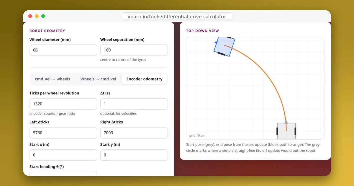
Wheel odometry estimates where a robot is by counting how far each wheel has turned. It is fast, cheap and smooth, which is why every mobile robot uses it, and it drifts, which is why no robot relies on it alone. This guide covers the computation from encoder ticks to pose, the integration choice that makes a surprising difference, how to publish odometry in ROS 2, and where its errors come from.
Step 1: ticks to distance
An encoder reports a count that changes as the wheel turns. Between two updates, each wheel's travel is:
Ticks per wheel revolution is the encoder's counts per motor revolution, times the decoding factor (×4 if you count every edge of both quadrature channels), times the gear ratio. Getting it wrong scales every distance. With 33 mm wheels and 1320 ticks per revolution, one tick is 0.157 mm.
Hardware counters overflow. A 16-bit counter wraps from 65535 to 0, so compute differences with wraparound in mind, as the tick_delta helper below does.
Step 2: distance to motion
From the two wheel distances, the robot's centre moved and turned by:
Step 3: motion to pose, and why the method matters
The simplest update moves the robot Δs along its current heading and then turns it by Δθ (an Euler step). But during the interval the robot actually followed an arc, so this cuts the corner. The exact update follows the arc:
How much does it matter? We took a 1 m arc (left wheel 0.9 m, right 1.1 m, 160 mm separation) and integrated it in different numbers of steps:
| Steps over the arc | Euler error | Midpoint error | Exact arc |
|---|---|---|---|
| 1 | 598 mm | 64 mm | 0 |
| 10 | 59 mm | 0.6 mm | 0 |
| 100 | 5.9 mm | 0.006 mm | 0 |
The "midpoint" method uses the heading halfway through the step, cos(θ + Δθ/2), and is nearly as good as the exact formula. At a typical 50 Hz update rate the steps are small, so even Euler is acceptable while driving; but after a dropped connection, a long processing stall, or when integrating logged data at a low rate, the exact update avoids a large, invisible error.
The code
import math


class WheelOdometry:
    def __init__(self, wheel_radius, wheel_separation, ticks_per_rev):
        self.m_per_tick = 2 * math.pi * wheel_radius / ticks_per_rev
        self.separation = wheel_separation
        self.x = self.y = self.theta = 0.0

    def update(self, d_ticks_left, d_ticks_right):
        dl = d_ticks_left * self.m_per_tick
        dr = d_ticks_right * self.m_per_tick
        ds = (dr + dl) / 2                      # distance moved by the axle centre
        dtheta = (dr - dl) / self.separation    # change in heading
        if abs(dtheta) < 1e-9:                  # straight line
            self.x += ds * math.cos(self.theta)
            self.y += ds * math.sin(self.theta)
        else:                                   # exact arc
            radius = ds / dtheta
            self.x += radius * (math.sin(self.theta + dtheta) - math.sin(self.theta))
            self.y -= radius * (math.cos(self.theta + dtheta) - math.cos(self.theta))
        self.theta = math.atan2(math.sin(self.theta + dtheta), math.cos(self.theta + dtheta))
        return ds, dtheta


def tick_delta(new, old, bits=16):
    """Difference between two readings of a counter that wraps around."""
    span = 1 << bits
    return (new - old + span // 2) % span - span // 2
We checked this class against the Differential Drive Calculator's odometry tab: for 5730 and 7003 ticks with 33 mm wheels, 160 mm separation and 1320 ticks per revolution, both give x = 0.7593 m, y = 0.5477 m and θ = 1.2498 rad, and splitting the motion into ten smaller updates gives the same result.
Publishing it in ROS 2
Odometry is published two ways, following REP 105:
- a
nav_msgs/Odometrymessage on/odom, withheader.frame_id=odomandchild_frame_id=base_link. The pose is in the odom frame; the twist (v and ω) is in the robot's own frame. Fill in the covariance fields honestly; filters such asrobot_localizationuse them to decide how much to trust the odometry; - the
odom→base_linktransform on TF, unless another node (such as an EKF) publishes it.
If you use ros2_control, diff_drive_controller already does all of this; see from cmd_vel to wheel speeds.
Where the errors come from
Systematic errors
Errors that repeat the same way every time: a wheel radius that is slightly wrong, unequal wheel diameters, a wheel separation that differs from the real effective value, misaligned wheels. They make the robot drift in a consistent direction and can be calibrated out, as described in calibrating wheel radius and separation.
Non-systematic errors
Random errors: wheel slip during hard acceleration or on smooth floors, bumps and uneven ground, tyres compressing differently under changing load. They cannot be calibrated away, and they accumulate.
Heading error dominates
A small error in heading turns into a growing sideways error with every metre travelled. A heading error of just 1° puts the robot about 17 cm off to the side after 10 m. This is why the most effective upgrade to wheel odometry is a gyro: fusing an IMU's yaw rate with the wheel odometry (for example with robot_localization) usually improves heading far more than any amount of encoder resolution.
Odometry's job
Odometry is the short-term, smooth estimate: excellent over a few metres and the backbone of local control. Over longer distances, a localisation system (AMCL against a map, or SLAM) corrects its drift by publishing the map → odom transform. Good odometry makes that correction small and the robot's motion smooth.