In ROS 2, everything that wants a robot to move, from a teleop keyboard to the Nav2 navigation stack, publishes a velocity command on a cmd_vel topic. Something has to turn that command into two wheel speeds and send them to the motors. This guide follows a command from the topic to the wheels, using the standard diff_drive_controller from ros2_control, with the parameter names and message types checked against ROS 2 Jazzy.
The command
A velocity command carries a linear and an angular velocity. A differential-drive robot uses only two of the six fields: linear.x (forward speed in m/s) and angular.z (turn rate in rad/s, positive to the left). The others are ignored, because the robot cannot move sideways or tilt.
On ROS 2 Jazzy, diff_drive_controller subscribes to ~/cmd_vel as geometry_msgs/TwistStamped only; there is no option to accept a plain Twist. A tool publishing Twist appears to work (the topic shows up) but the robot never moves. Teleop keyboard needs -p stamped:=true; Nav2's controller server has an enable_stamped_cmd_vel parameter; and the twist_stamper package converts between the two when a tool has no option.
From command to wheel speeds
The controller applies the inverse kinematics explained in our kinematics guide:
and writes the two results, in radians per second, to the wheels' velocity command interfaces. Your hardware interface, or the microcontroller behind it, then runs a speed loop on each motor to hold those speeds, as in our guide to closed-loop motor speed control.
Configuring diff_drive_controller
A minimal configuration for a robot with 100 mm wheels 300 mm apart:
controller_manager:
  ros__parameters:
    update_rate: 100
    diff_drive_controller:
      type: diff_drive_controller/DiffDriveController
    joint_state_broadcaster:
      type: joint_state_broadcaster/JointStateBroadcaster

diff_drive_controller:
  ros__parameters:
    left_wheel_names: ["left_wheel_joint"]
    right_wheel_names: ["right_wheel_joint"]
    wheel_separation: 0.30
    wheel_radius: 0.05
    odom_frame_id: odom
    base_frame_id: base_link
    enable_odom_tf: true
    publish_rate: 50.0
    cmd_vel_timeout: 0.5
    linear.x.max_velocity: 1.0
    linear.x.max_acceleration: 0.8
    angular.z.max_velocity: 2.0
angular.z.max_acceleration: 3.0left_wheel_names/right_wheel_namesmust match the joint names in your URDF and hardware interface. Lists allow several wheels per side, such as skid-steer robots.wheel_separationandwheel_radiusare the kinematic constants. Thewheel_separation_multiplier,left_wheel_radius_multiplierandright_wheel_radius_multiplierparameters apply calibration corrections without editing the measured values; see calibrating wheel radius and separation.cmd_vel_timeout(seconds): if no command arrives for this long, the controller commands zero. Keep it short; it is your protection against a crashed planner.- Limits: the
linear.x.*andangular.z.*groups cap velocity, acceleration and jerk, discussed in our guide to velocity and acceleration limits.
Odometry comes back the other way
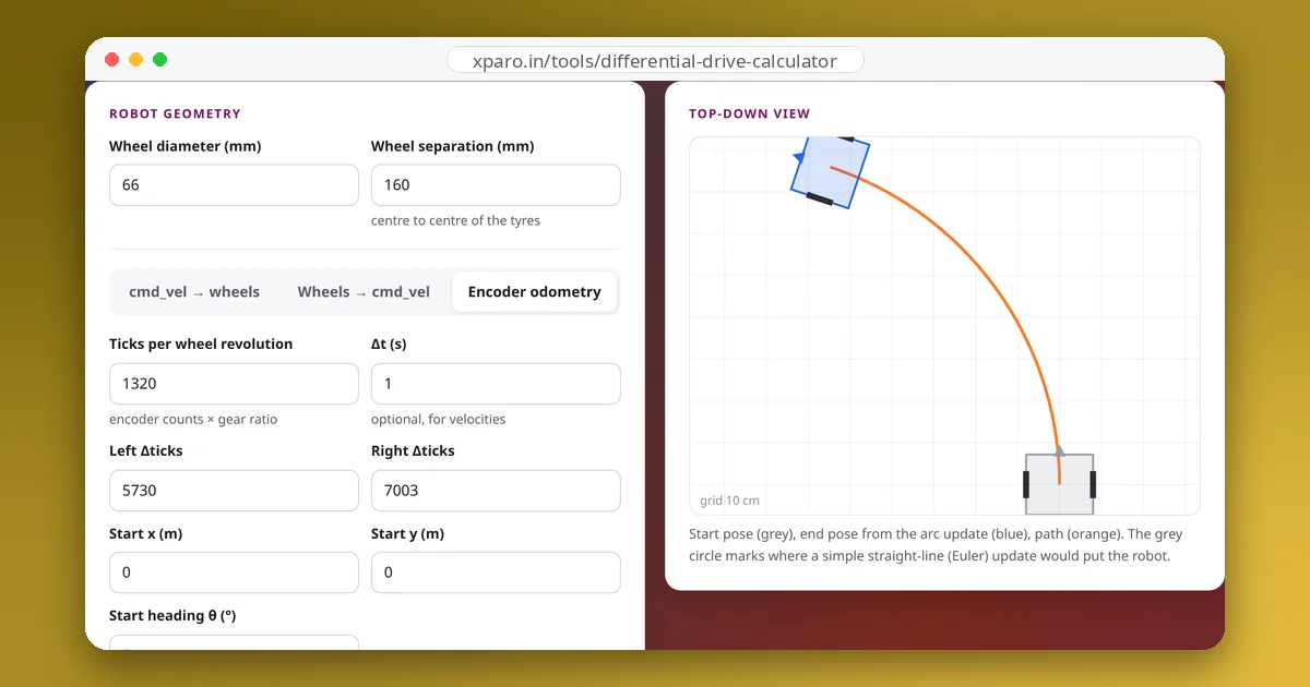
The same controller reads the wheels' measured positions (or velocities, if position_feedback is false), applies the forward kinematics, integrates the robot's pose and publishes it on ~/odom as nav_msgs/Odometry, and, with enable_odom_tf, as the odom → base_link transform. If another node (for example robot_localization fusing an IMU) publishes that transform, set enable_odom_tf: false so two publishers don't fight. With open_loop: true, odometry is computed from the commanded velocities instead of the measured ones, which is only acceptable when there are no encoders.
Topic names
The controller's topics live under its own name: /diff_drive_controller/cmd_vel and /diff_drive_controller/odom. Most other software expects /cmd_vel and /odom, so remap them, typically in the launch file that starts ros2_control_node, or point Nav2 and your teleop tool at the controller's names directly.
Testing the chain
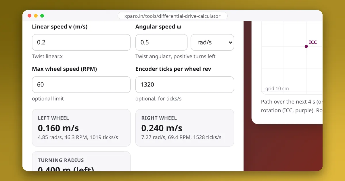
# drive forward at 0.2 m/s while turning left at 0.5 rad/s (stamped, for Jazzy)
ros2 topic pub --rate 10 /diff_drive_controller/cmd_vel geometry_msgs/msg/TwistStamped \
  "{twist: {linear: {x: 0.2}, angular: {z: 0.5}}}"

# what the controller sends to the wheels
ros2 topic echo /joint_states
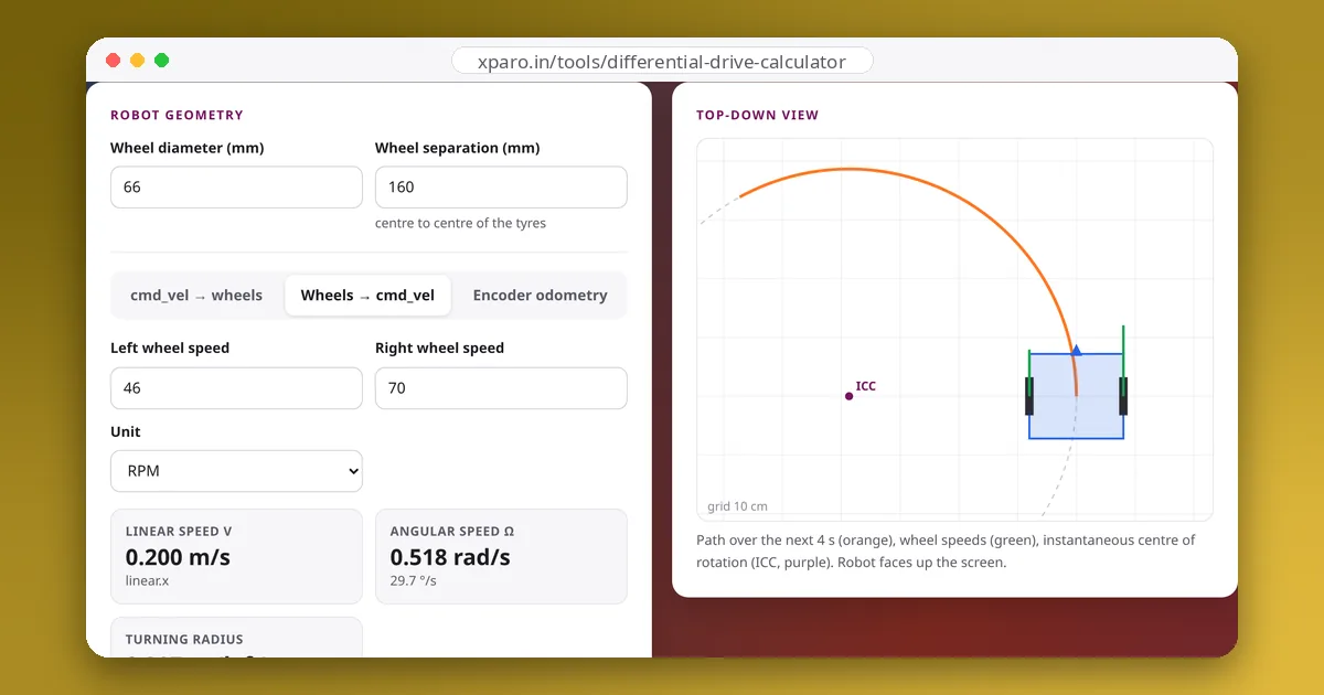
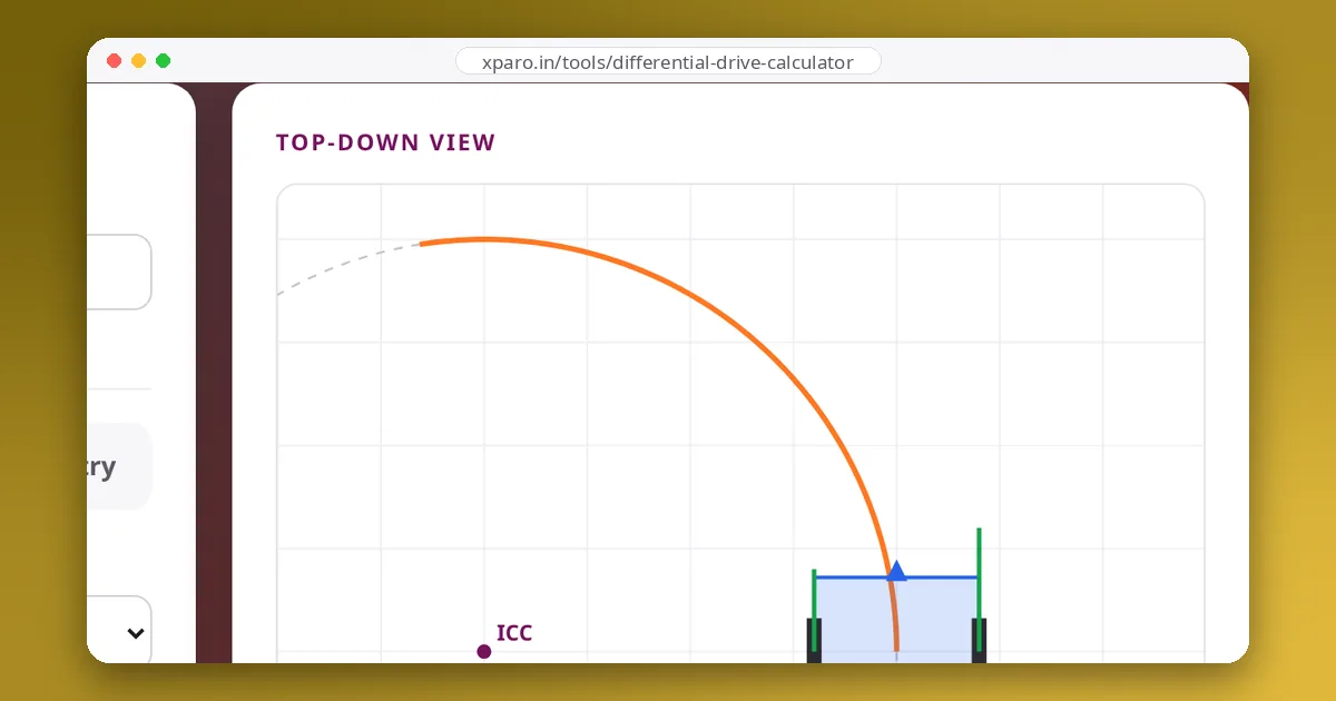
Compare the wheel velocities with the Differential Drive Calculator: enter your radius and separation, the same v and ω, and the left and right wheel speeds should match. A sign flip (the robot turns right when told to turn left) usually means the left and right wheel names are swapped, or one motor's direction is inverted in the hardware interface.
Without ros2_control
If your robot uses a microcontroller and a custom bridge instead, the bridge does the same conversion itself, as in the bridge node in our serial protocol guide. Keep the same safety habits: a timeout that stops the robot, limits on speed and acceleration, and odometry computed from measured wheel motion.